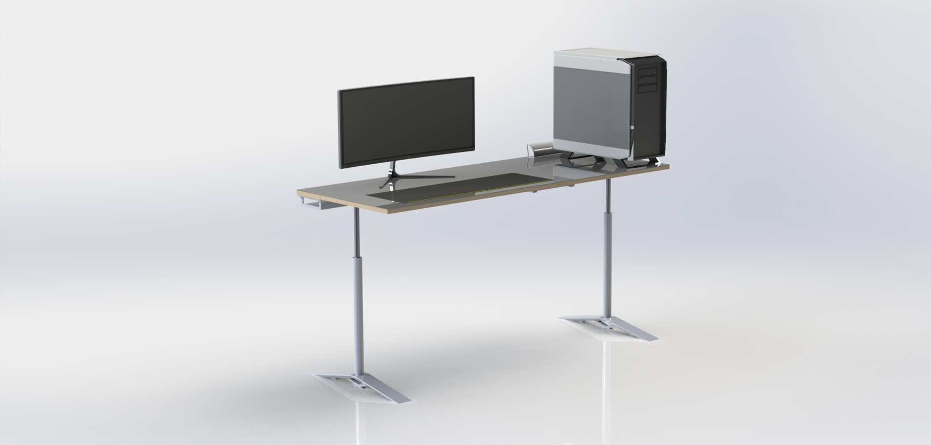
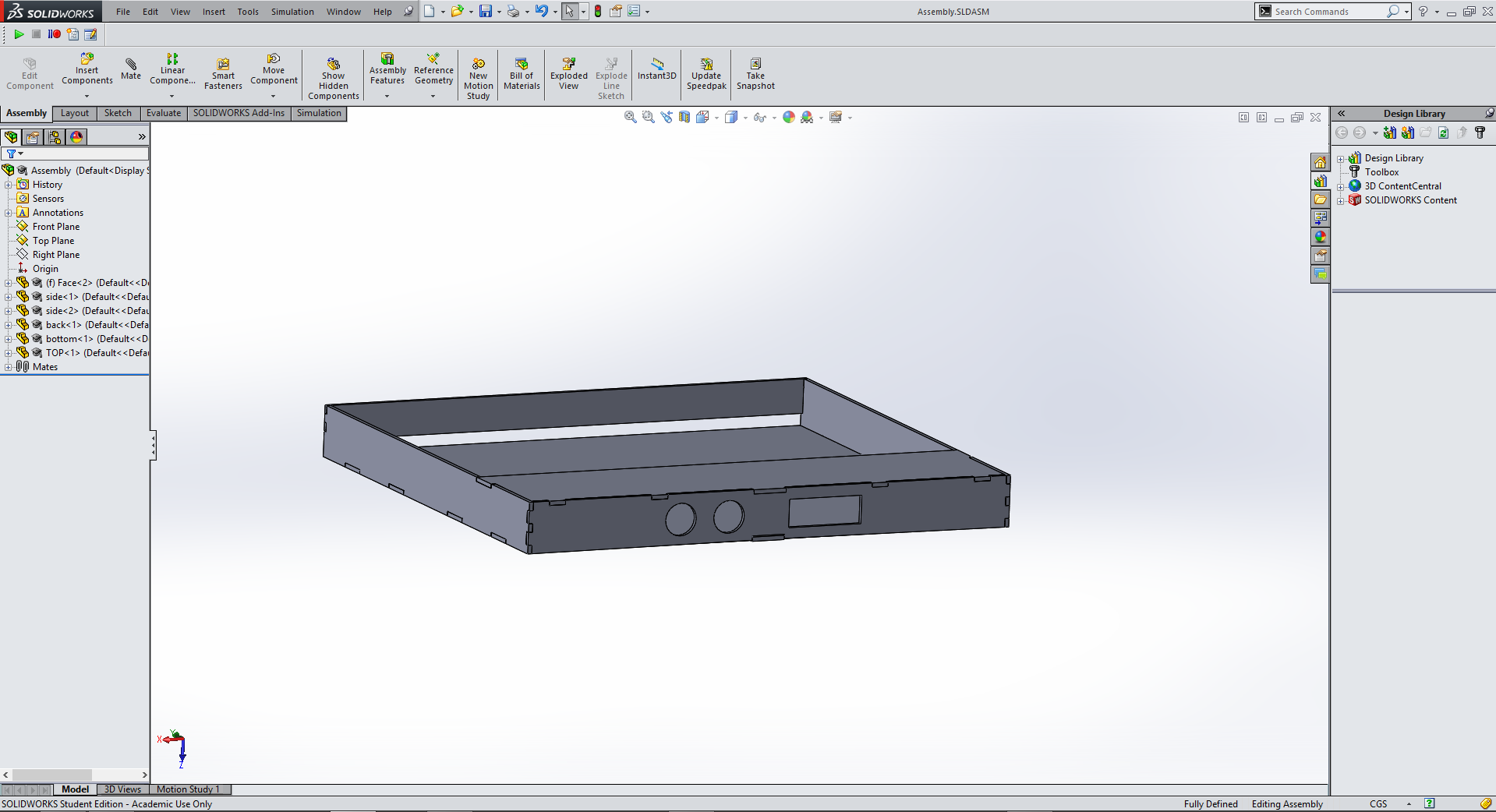
For my new final project I want to build a standup desk that can lower to a sitting height or raise to a few different standing desk heights. The render above shows the desk with a computer sitting ontop. I plan to use linear actuators to raise and lower the desk and a CNC machine to cut the desk surface and feet. I want to use a high quality plastic to cover the wooden top surface of the desk to protect it and provide a good working surface, but in order to still be able to use a mouse I am also going to inlay a mousepad for my keyboard and mouse to sit on. I also plan to add features such as a built in ethernet switch and cable routing channels on the bottom to create what will hopefully be my dream desk. |
This project will be licensed under the Creative Commons Attribution Non-commercial Share Alike License to protect it from commercial production while allowing it to be available to hobbiests and makers like myself. |
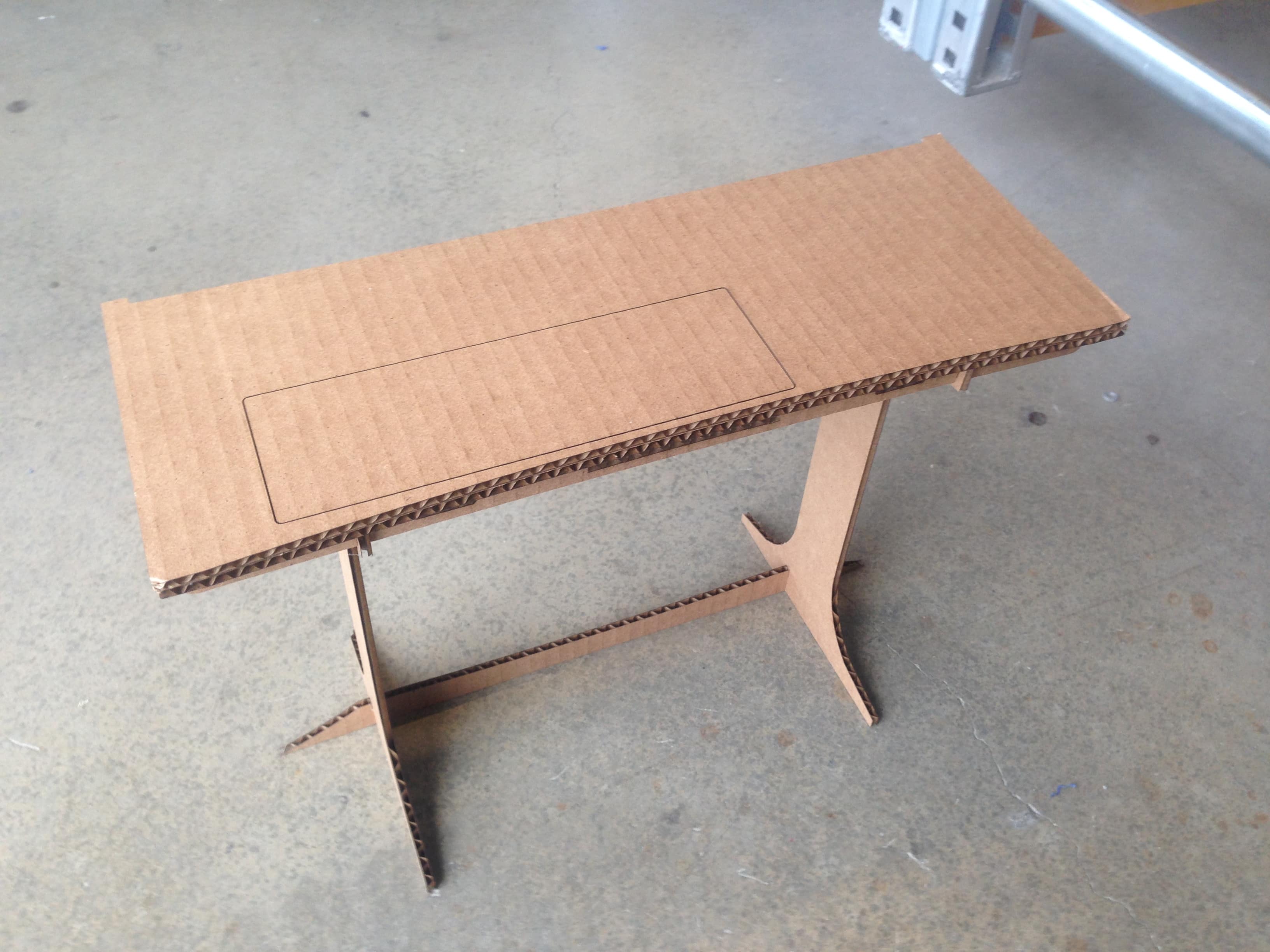
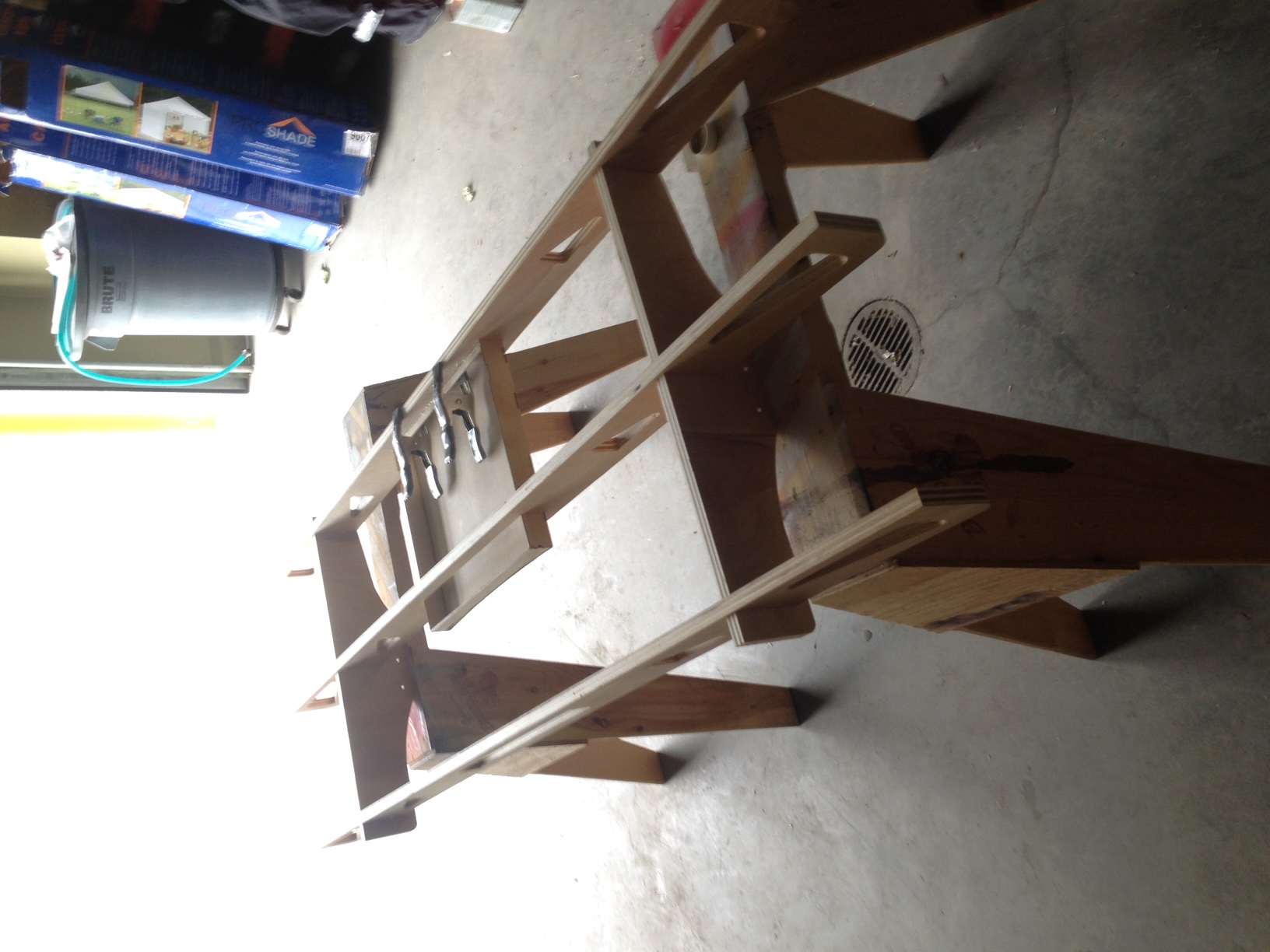
The next step I took in my final project was to create a cardboard scale model of my desk design out of cardboard. The legs do not adjust in length on the cardboard model, but other than that it is almost identical to my design above. |
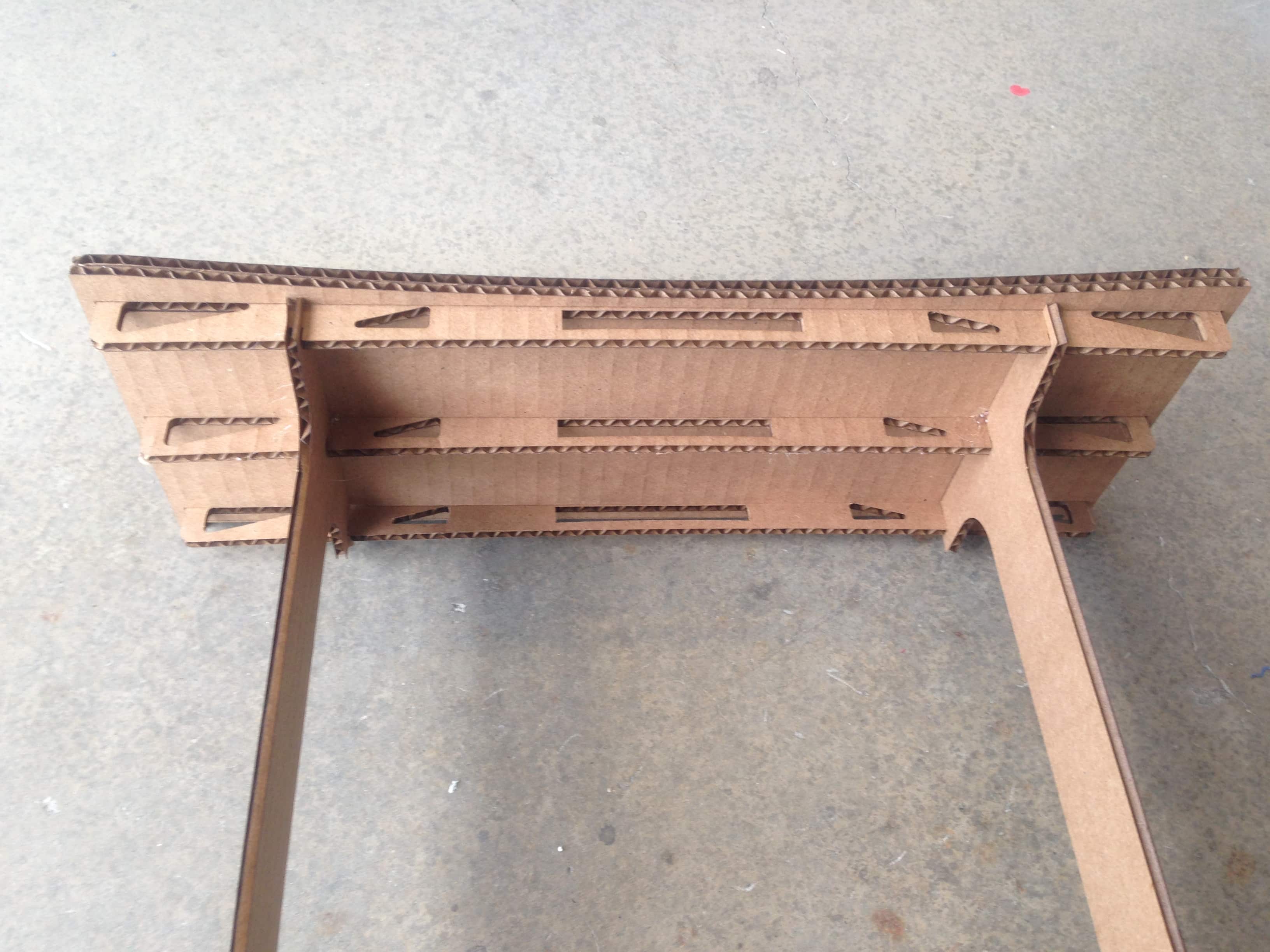
One feature that I did change based on my weekly project non-adjustable project you can see here under week 7, is supports running left to right on the bottom of the desk. These supports add more ridgidity to the desk surface which was an issue on my first desk. |
Worklog
Now, as I start actual work on my final project, I have a few challenges facing me. First, I have less than a week to finish my final project because I am headed out of town on a family vacation. Second, I have done almost nothing for my final project already except for a little bit of work in composites creating a mount for one of the linear actuators I will be using. In order to get everything done I plan to spend at least 10 hours at the lab every day for the next 4 days. I will do software and design work as well as website work at home and all physical making/manufacturing at the lab. Lets get started! |
This project will be licensed under the Creative Commons Attribution Non-commercial Share Alike License to protect it from commercial production while allowing it to be available to hobbiests and makers like myself. |
Day 1
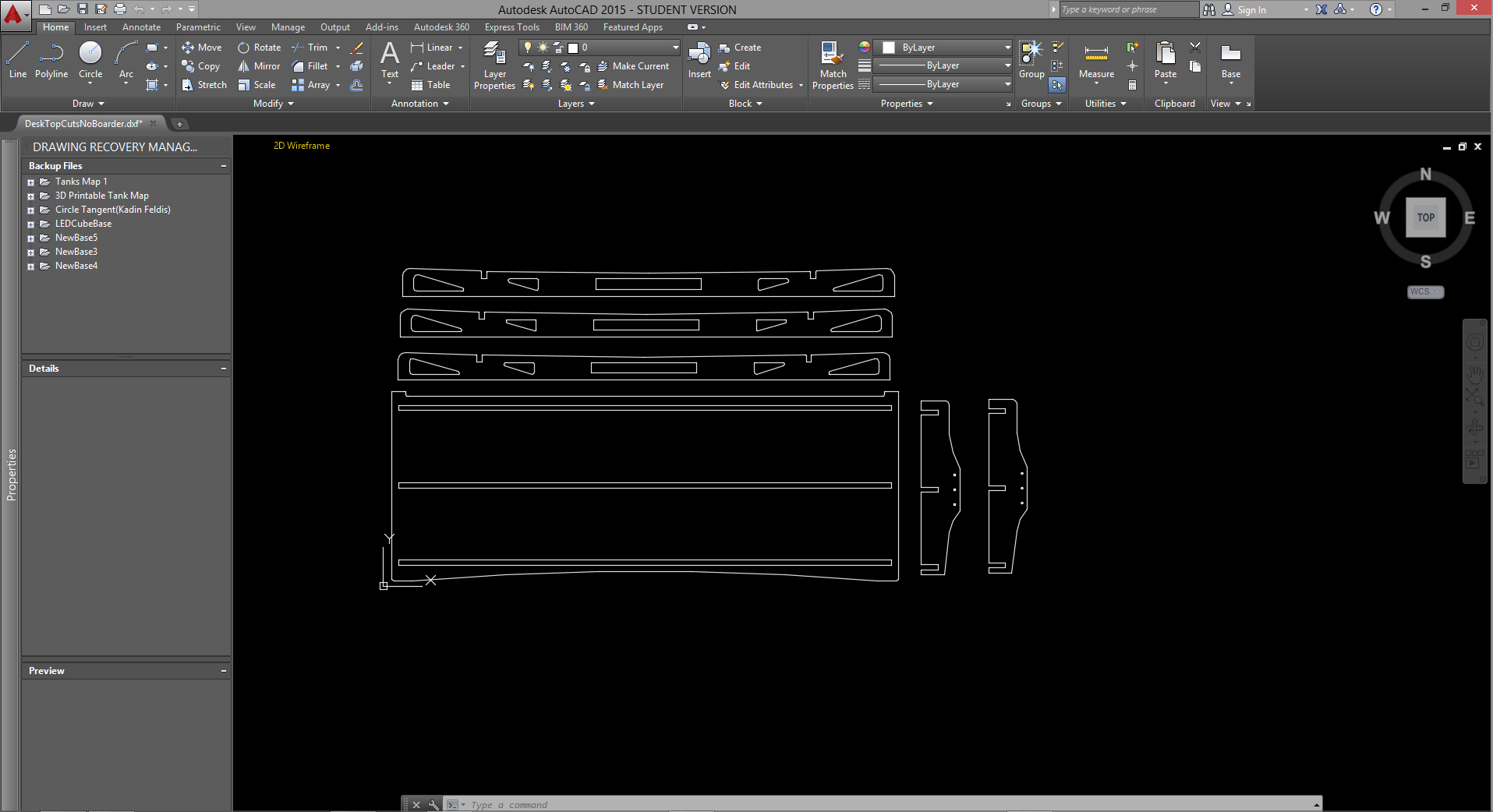
The first thing I did today was to layout the vectors of the parts for the top of the desk in AutoCAD so I could get the Shopbot started ASAP. |
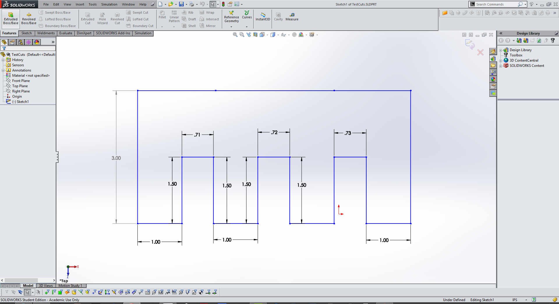
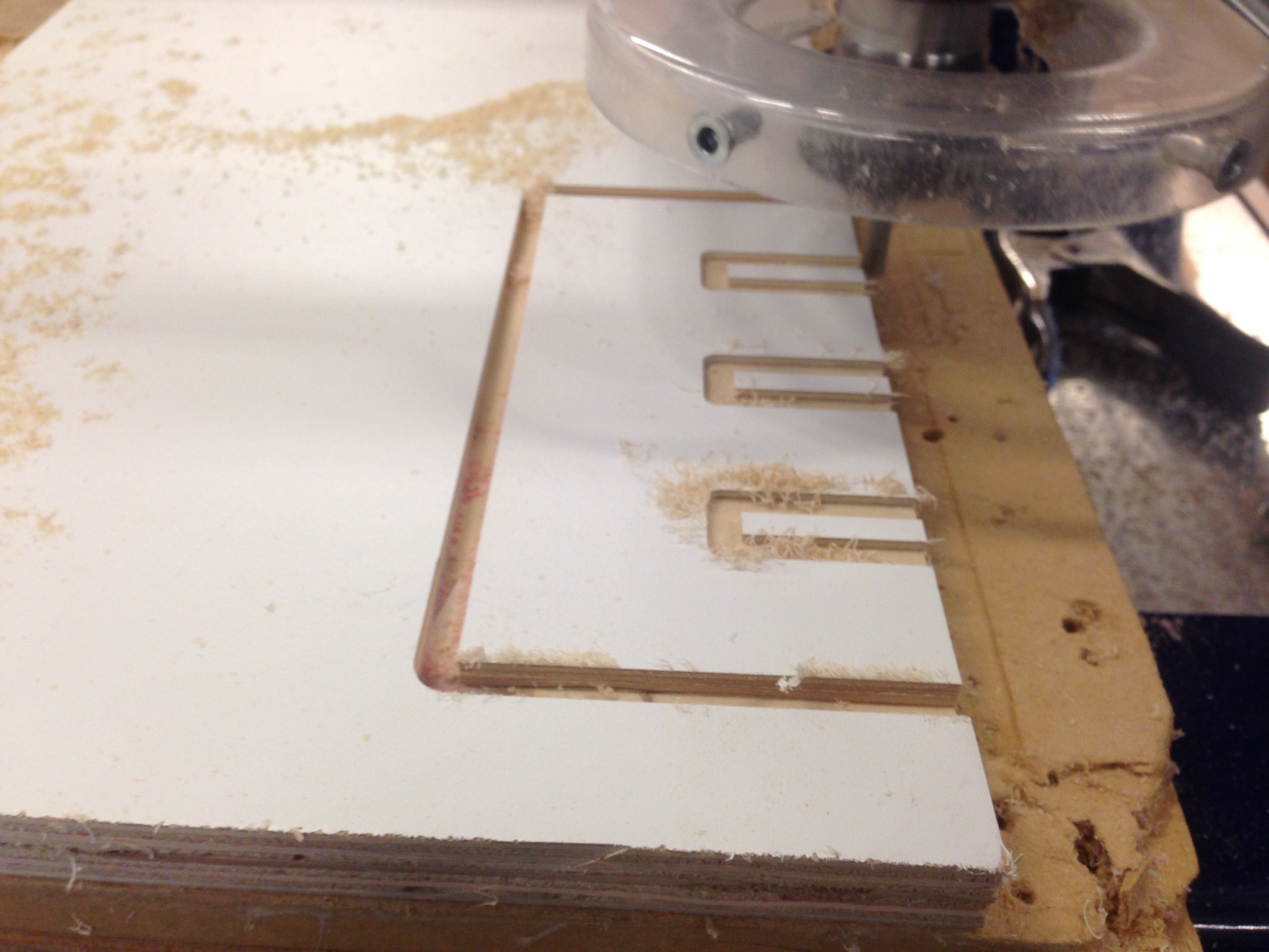
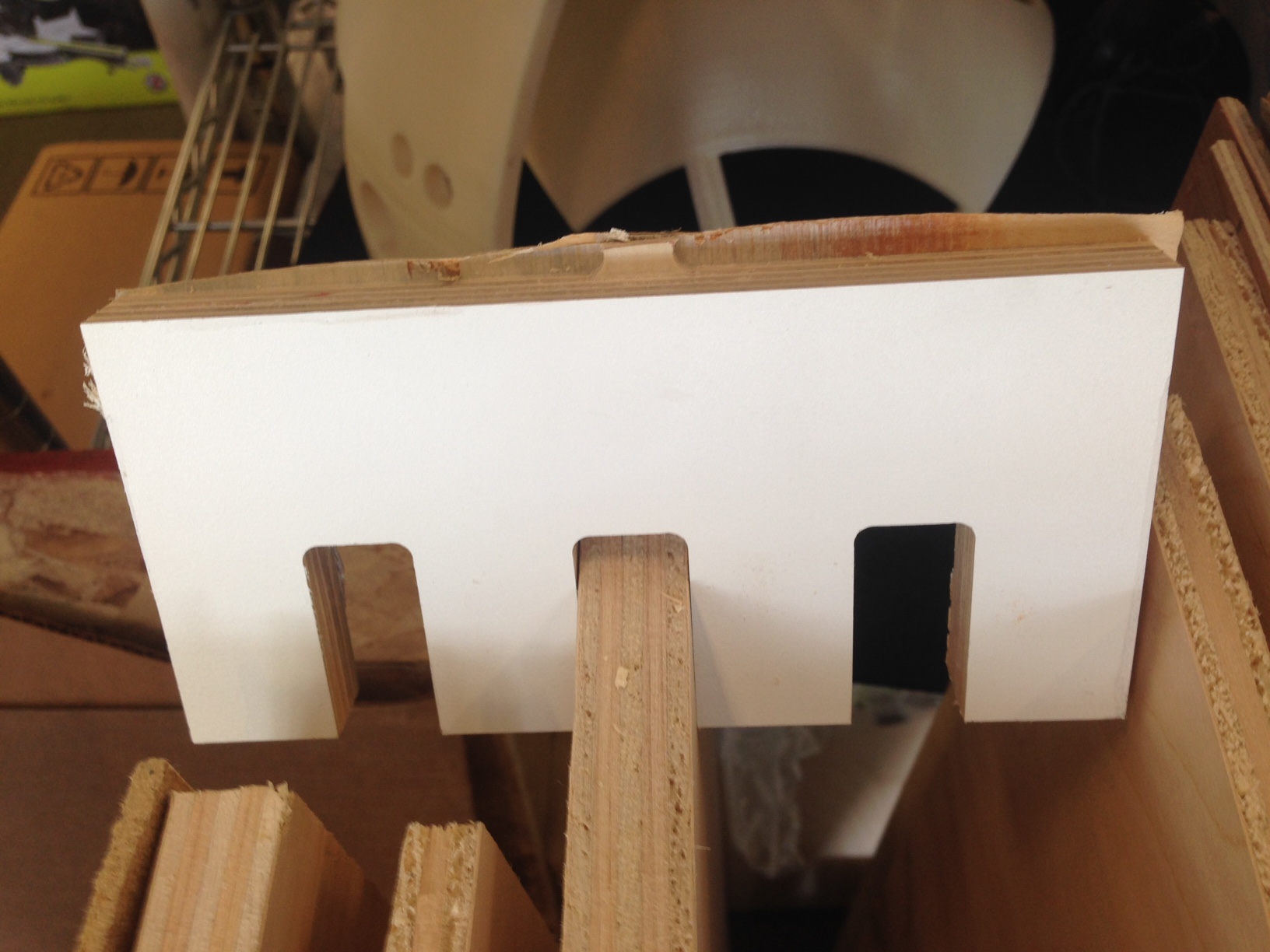
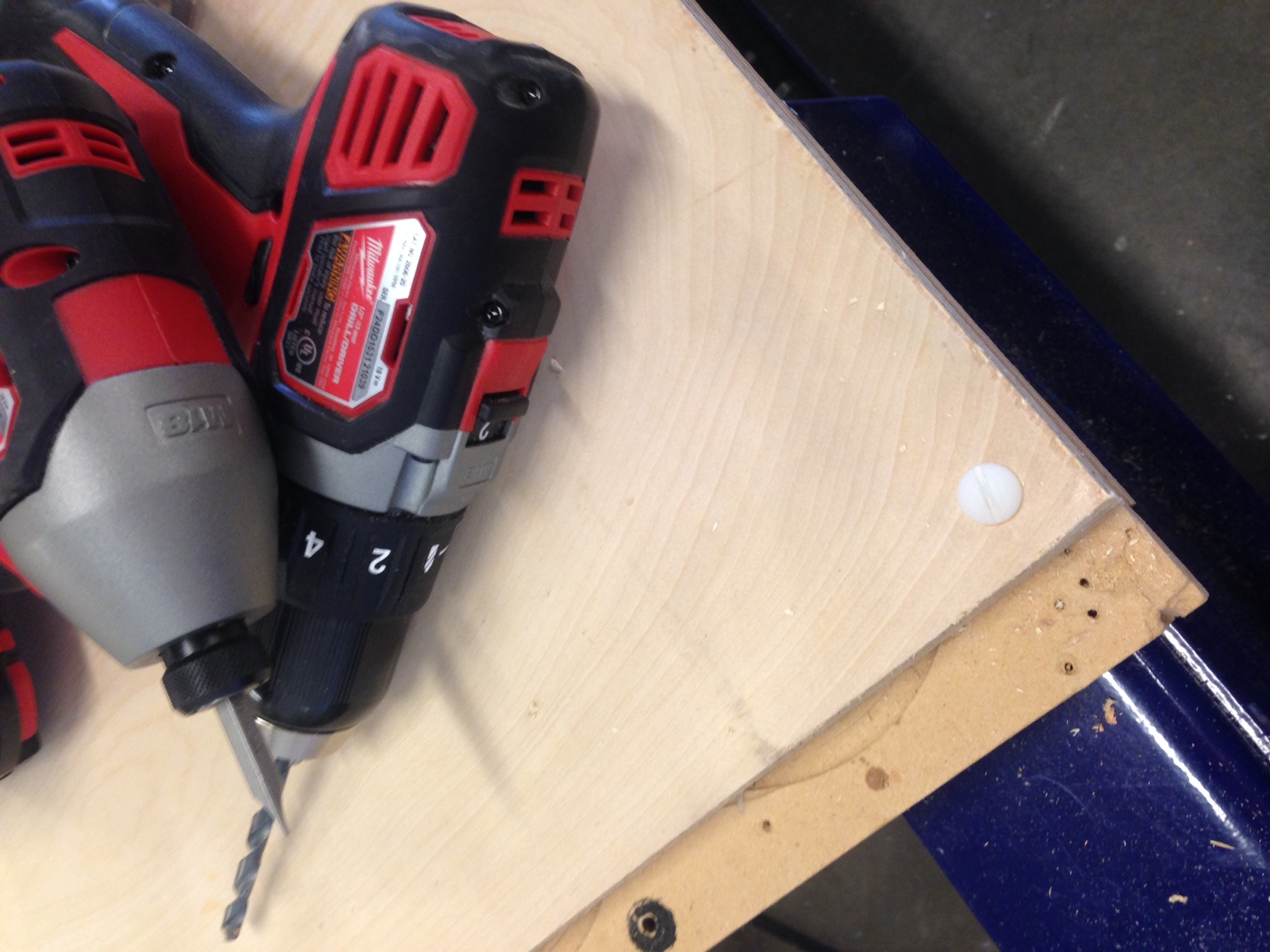
Before I started cutting those parts I created a test cut design in Soliworks to test good pressfit notch sizes for the 3/4" plywood I would be using. I cut this design out of a scrap piece of press board and used it to dermine that 0.72" wide notches would work best for my 3/4" finished plywood. |
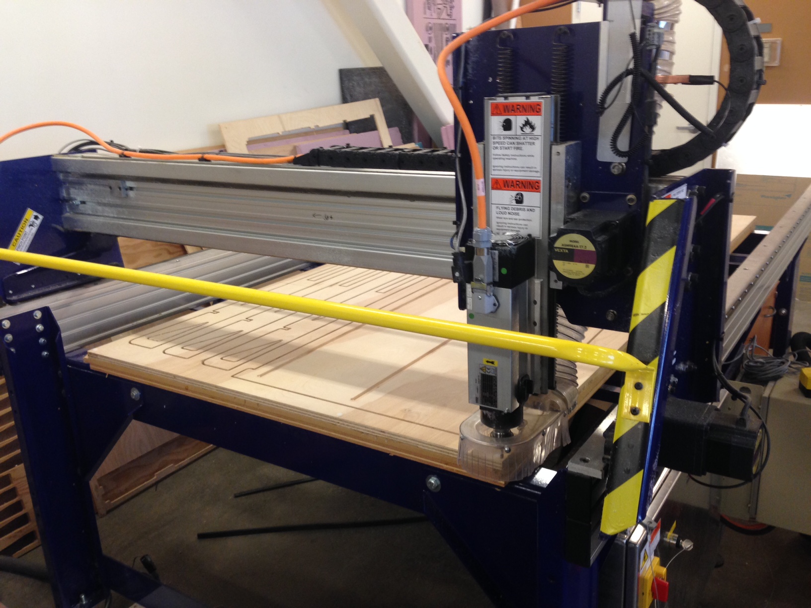
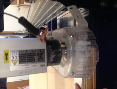
Then I attached the 4x8' piece of 3/4" plywood to the Shopbot and secured it with plastic screws, so that if the bit on the Shopbot hit one it would simply cut through the screw and would not break the expensive bit. Finally, I zeroed the X, Y, and Z axis. |
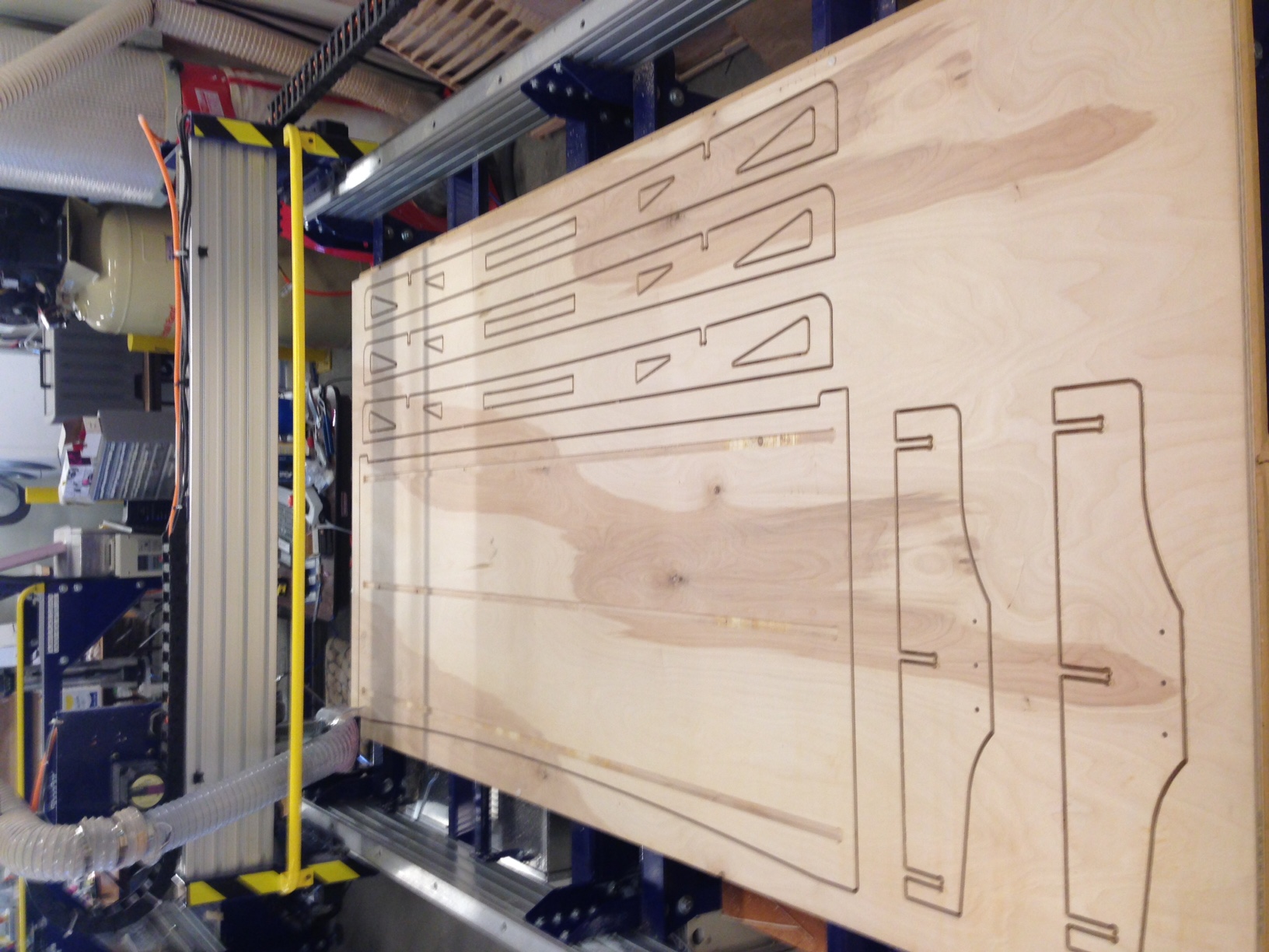
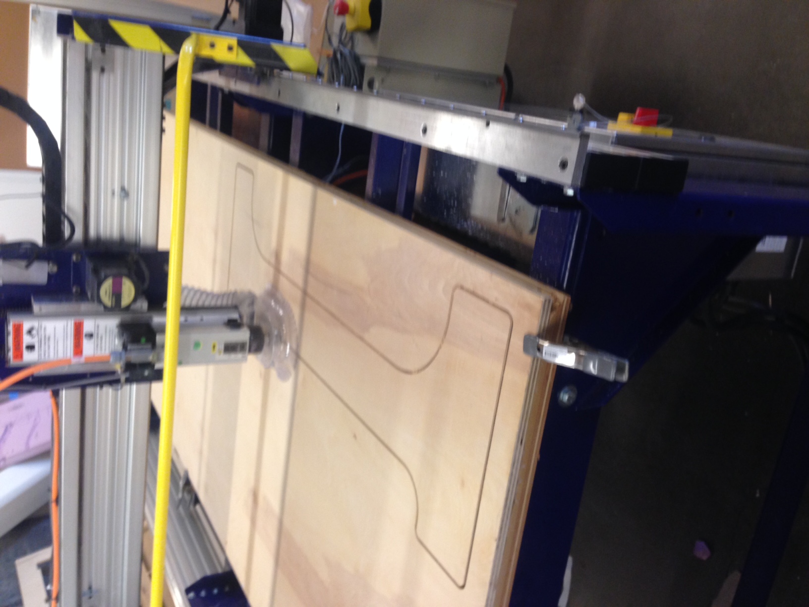
Then warmed out the Shopbot and started cutting out the from I put together in AutoCAD as seen in the first picture of the day. I used standard settings 65 inches per minute, 18000 rpm, etc, except in the cutfile I set the number of passes to 5 instead of 3 or 4 to get a very clean cut on my final desk. I also added dogbones in Aspire because there is an easy to use tool for it. Dogbones basically created circular cuts where there is an interior 90 corner so that your pieces will fit together and there will not be unwanted fillets created by the limitations of a round tooling bit. |
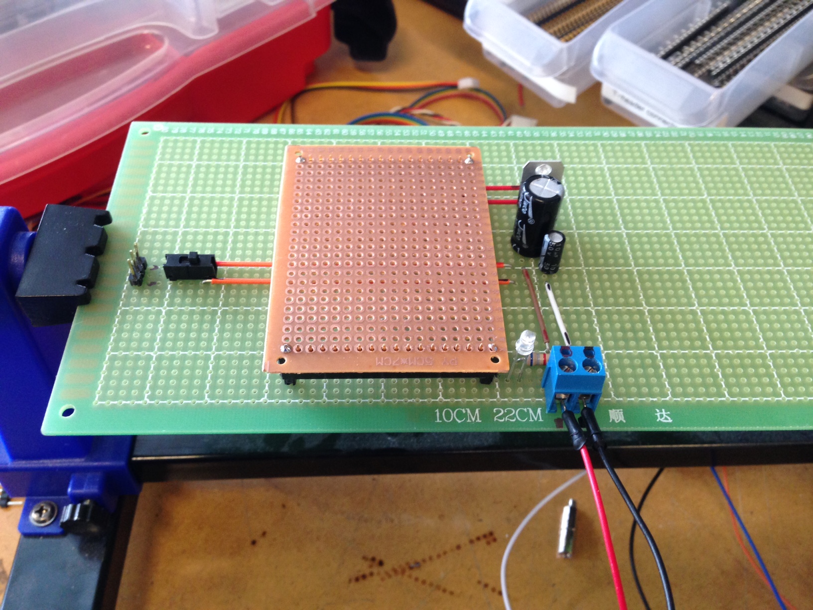
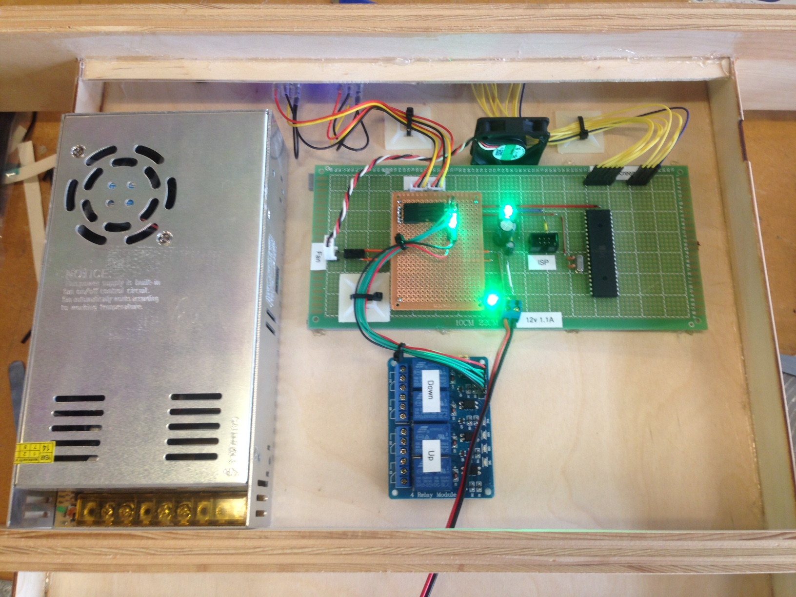
While the plywood was being cut I started work on the circuit that would control my desk. I decided to use a proto board rather than milling out the circuit for two reasons. Firstly, I had very little time to finish the project and did not thing I could design and mill a circuit as quickly as I could solder one on a proto board, and secondly because the lab did not have all of the components I wanted to use and I only had through hole components. Today I was able to get the stepdown 12V to 5V circuit for the microprocessor done, as well as a header for a 40mm fan and two status LEDs. One for 12v and one for 5v. |
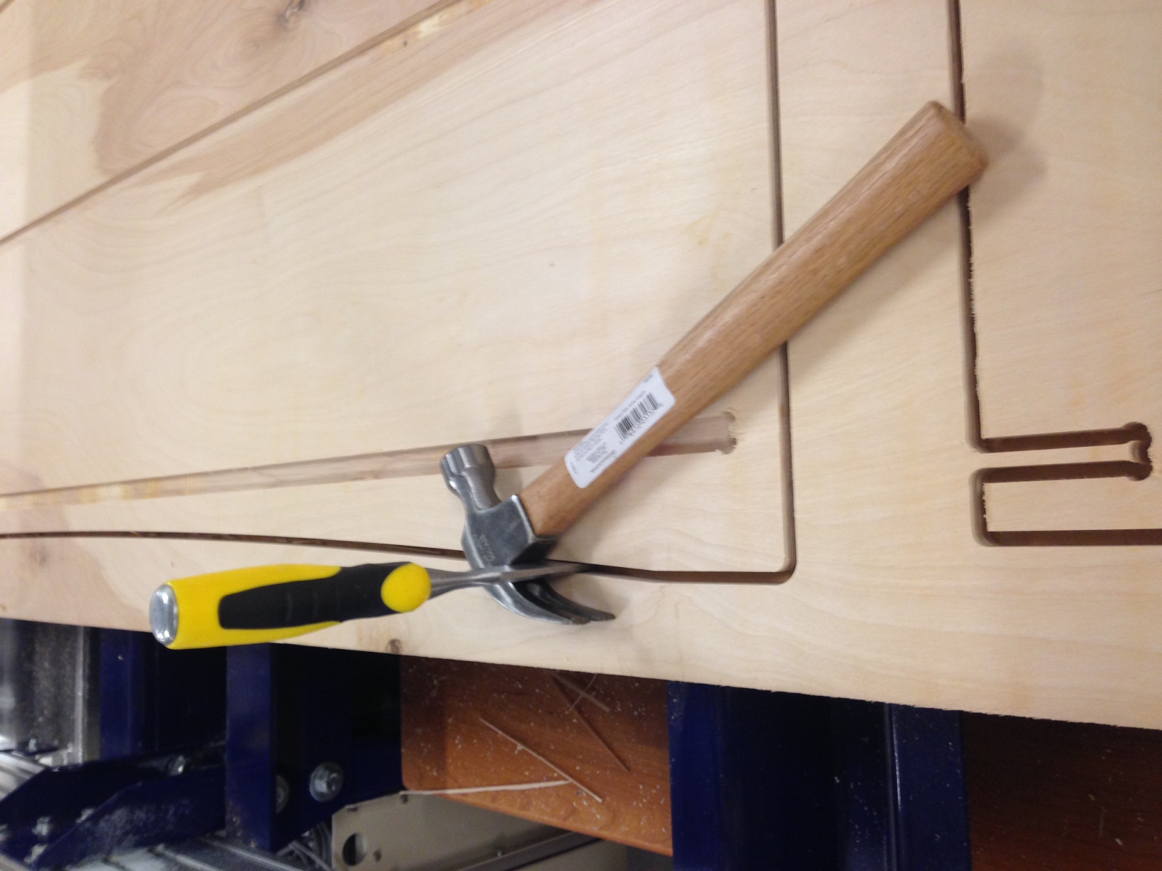
When the cuts on the Shopbot were done I used a chisle and hammer to break the tabs so I could remove the pieces. |
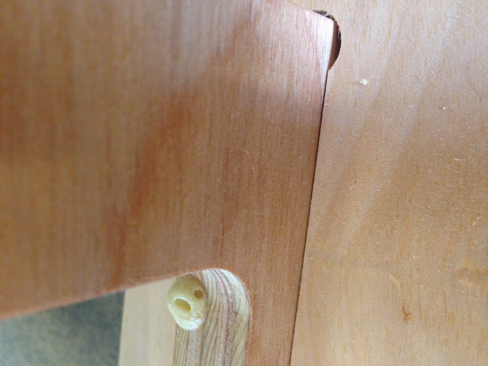
Finally I sanded off the remained parts of the tabs and finished off the edges with sandpaper so I could test the press fits. I glued the back horizontal support beam onto the bottom of the desk surface with woodglue and a few dabs of gorilla glue and the press fit was so good that the glue ended up coming out of crevices in the plywood not out of the edges of the joint. As you can see above it was a good fit thanks to the test cuts. You can also see part of one on the dogbones I mentioned earlier. |
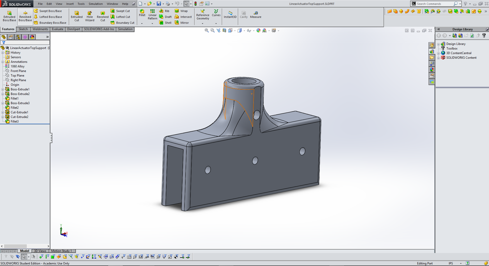
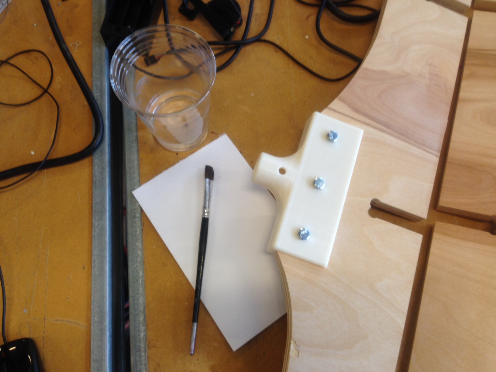
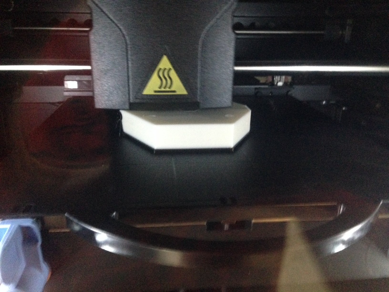
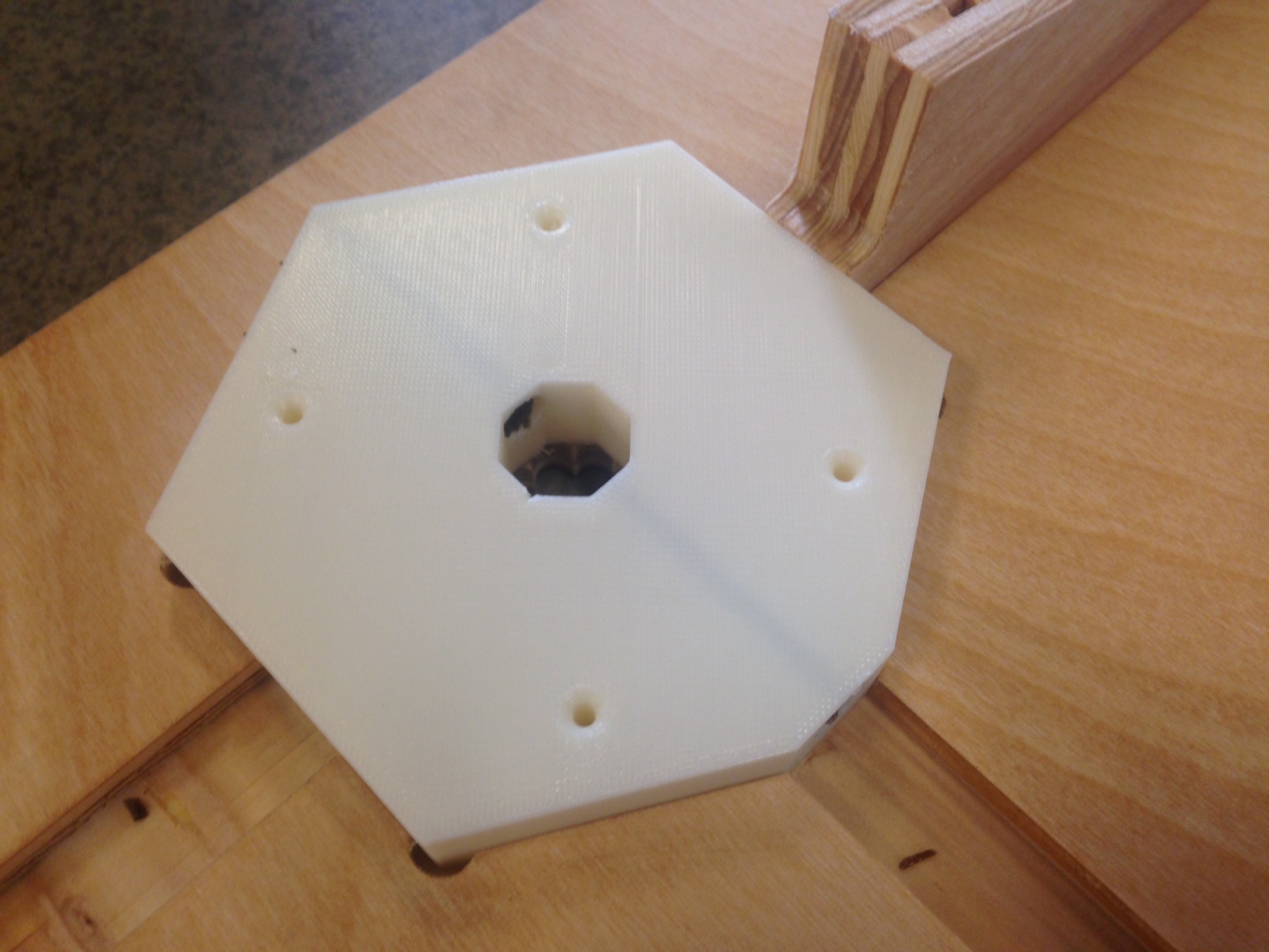
I also started printing two brackets that will attach the top of the linear actuators to the top of my desk. |
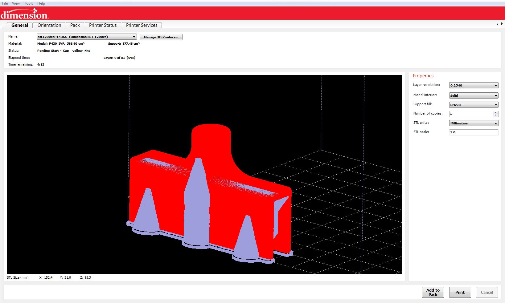
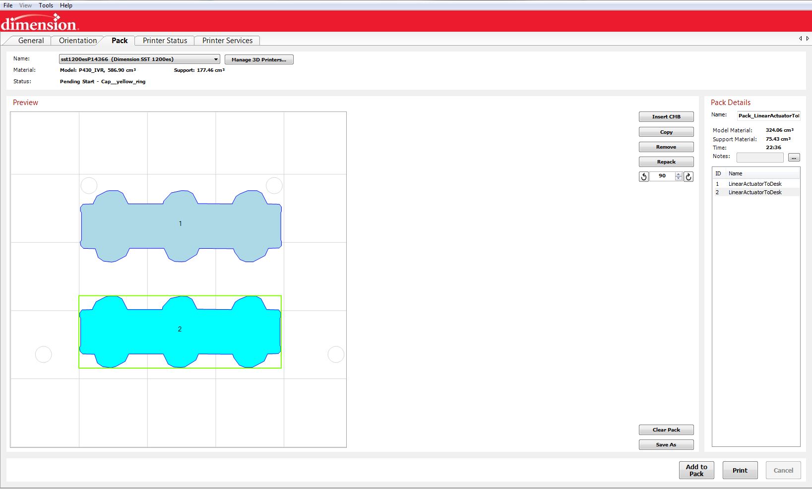
For these two prints I used the more expensive option for printing in our lab, the Stratus Systems, Dimension printer. I did this for two reasons. I wanted my prints to come out as accurate as possible, and I wanted strong ABS parts so that I could chemically bond the layers together with acetone. |
Day 2
I today off by rubbing down all of the parts for the top of my desk with a wood varnish to bring out the grain of the wood and protect the wood against moisture. |
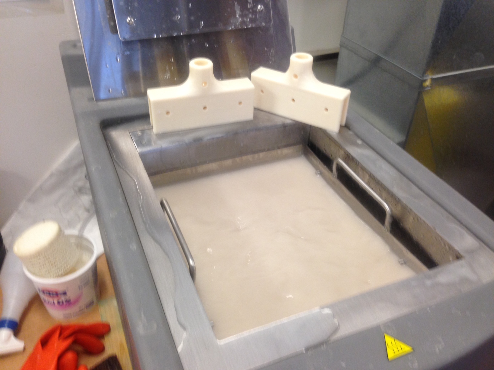
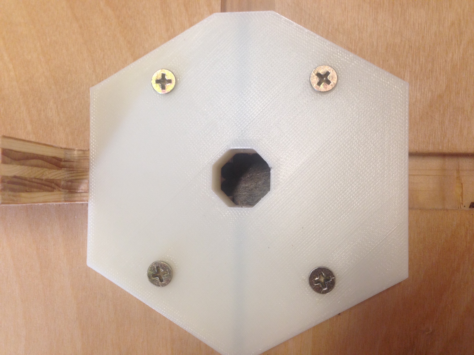
Then I removed the 3d printed brackets I put in the dissolving bath first thing in the morning to dissolve all of the support material in the bolt holes. |
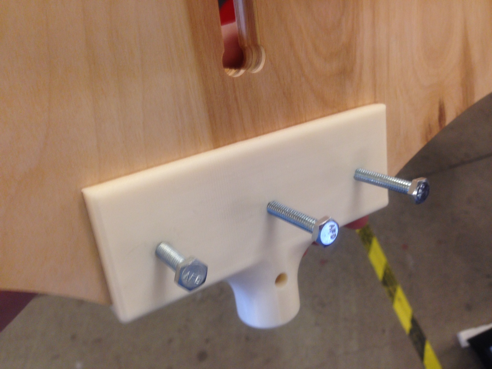
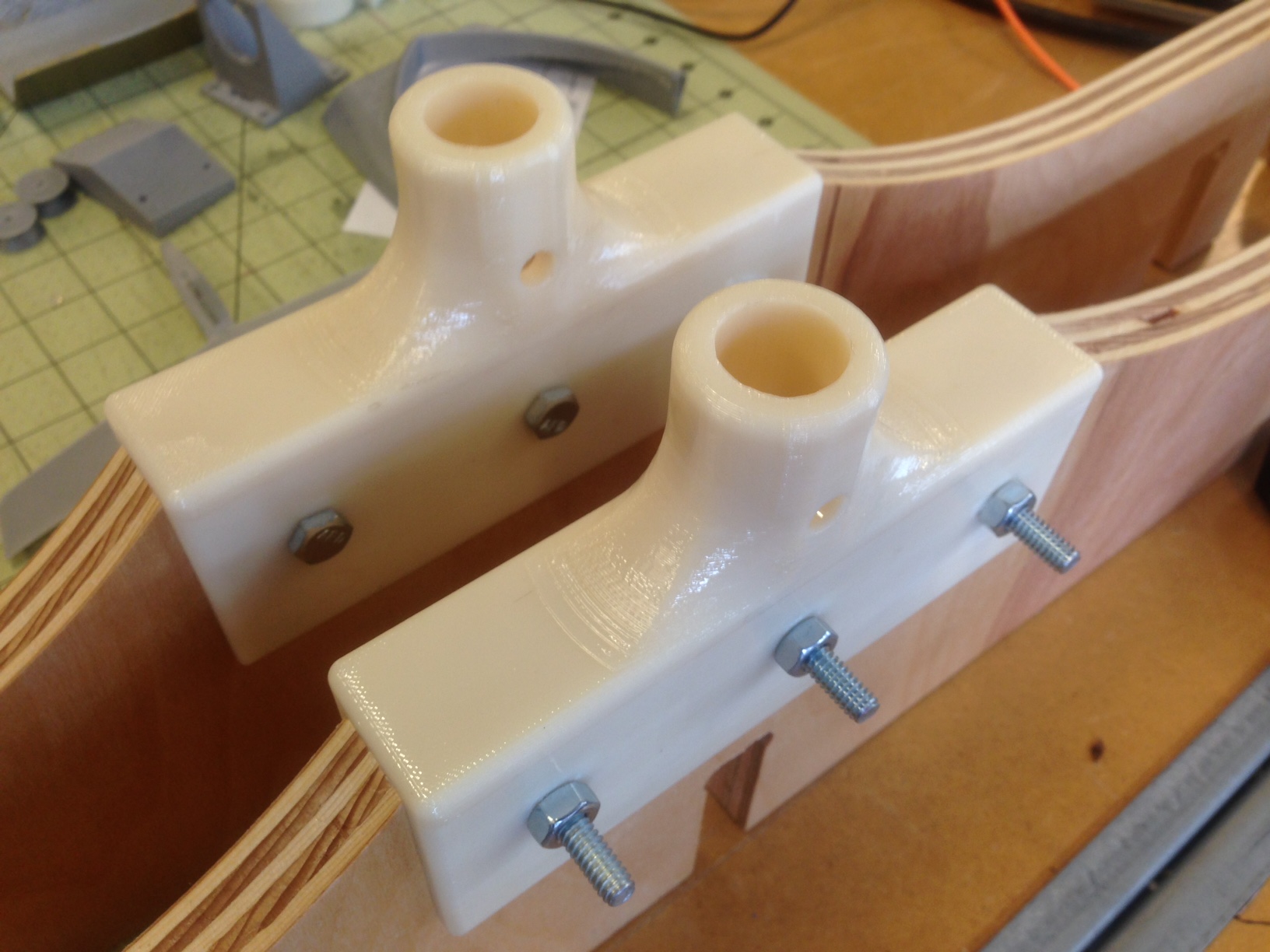
Then I tested them both and they both fit snuggly onto their plywood mounting points on the lateral support braces for the desktop. Once I knew they fit I used a small paint brush to brush them down, inside and out, with acetone to chemically bond the heat bonded layers of ABS together. This gave the parts a glosy look and made them stronger. |
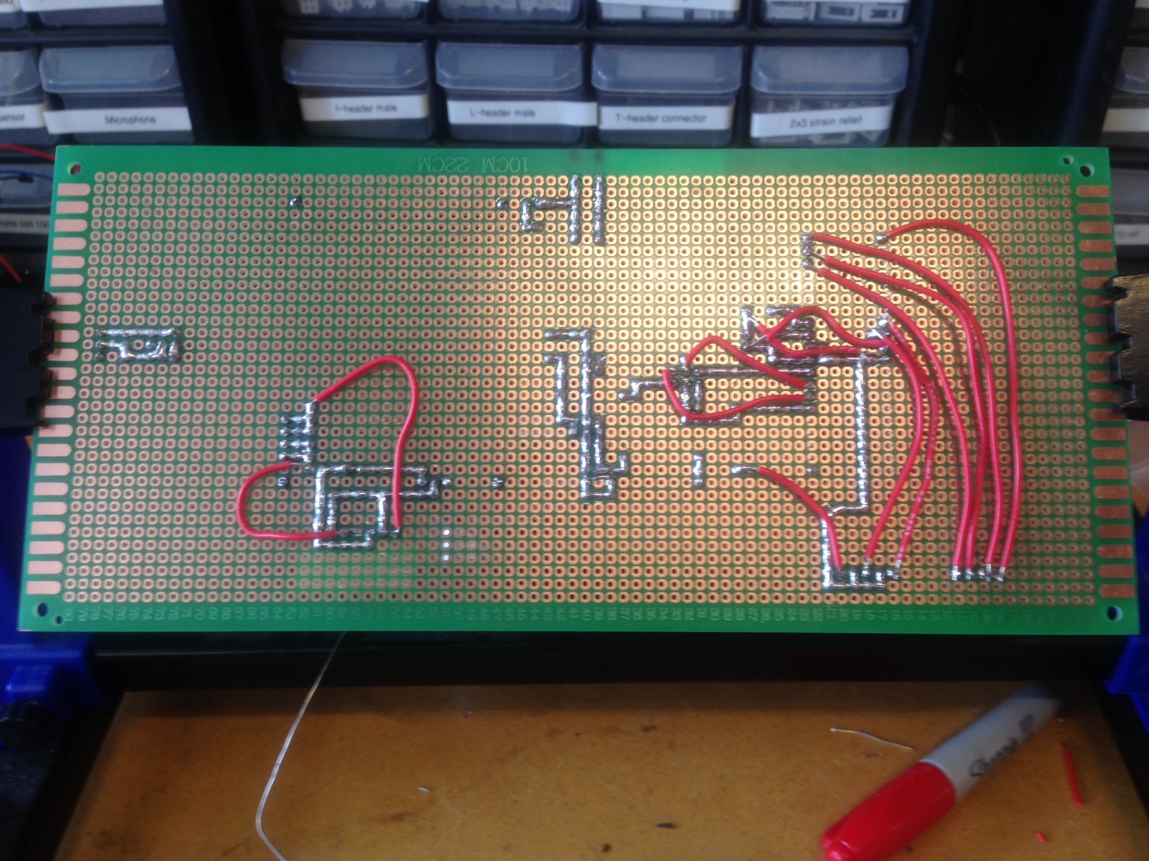
Lastly, I did some work on the electronics PCB for my desk. I added an Atmega324 microprocessor the handle the LCD, motion control, and hopefully some sensors in the future, as well as adding an ISP header to programming the microprocessor. |
Day 3
Today I started by laser cutting an electronics holder for all of the electronics in the desk. It is designed to slide into the middle notches in the horizontal support beams for the top of the desk. It has plenty of room for a power supply, my pcb, and sockets for mounting and LCD screen and two buttons to control the up/down motion of the desk. |
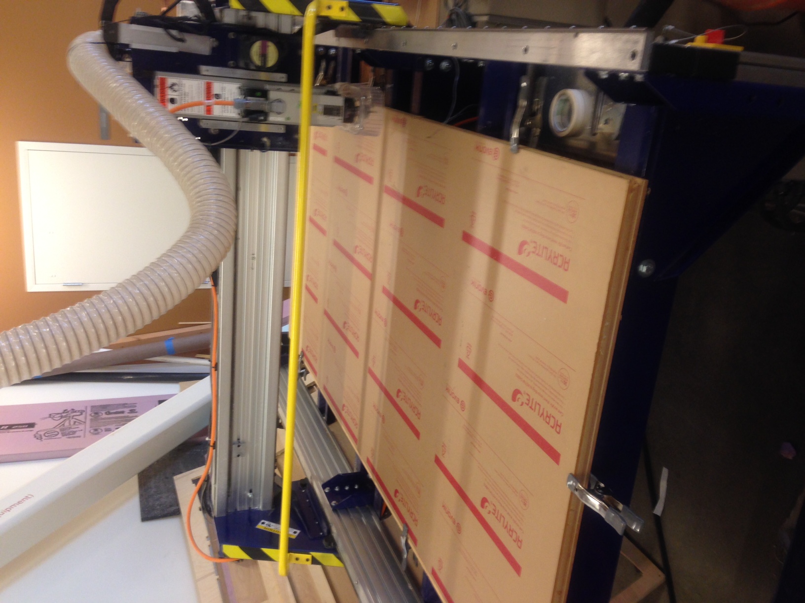
Then I started cutting the acrylic sheet that I am using to create the desk surface. It is a quarter inch clear acryclic to provide a protective, heat resistance surface that also shows of the grain of the wood beneath it. I used standard cut settings and a 1/4" endmill bit, except I changed the cut speed to 65 inches per minute and used 6 passes to ensure I got a clean cut in the acrylic. |
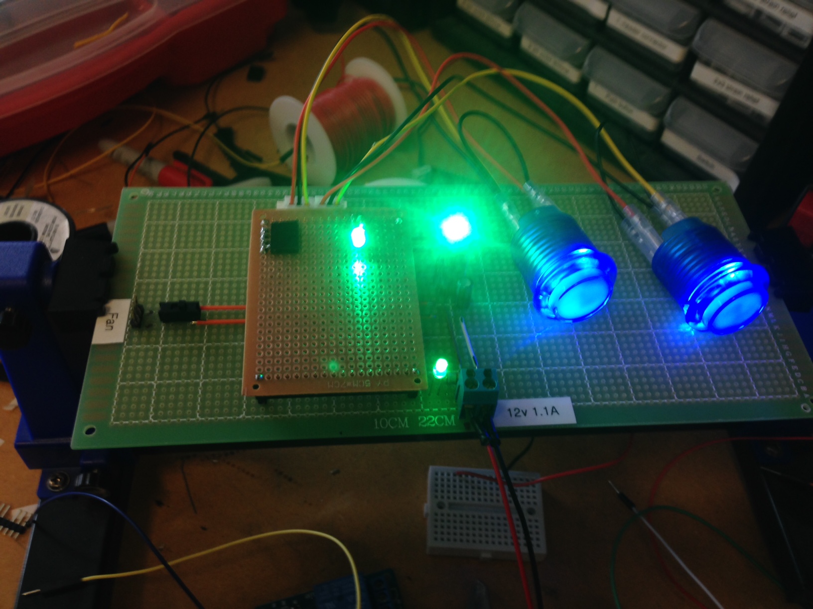
While that was cutting I finished up the main control PCB for my desk. I attach headers for the buttons and made sure they were working correctly and I added headers on the raised, brown PCB for the signal and power cable of the relay I will be using. |
Finally I started printing mounts for the bottom of the linear actuators on the same Stratus Systems printer I used to print the top mounts for the same reason. I wanted strong precise prints made out of ABS so that I could chemically bond the layers together. |
Day 4
Today I started the day off by cutting out the base of my desk on the shopbot. The base connects to the linear actuator and keeps the desk standing upright. |
While the base was cutting I finalized my circuit and added the relay that would control the linear actuators. Then I tested the 12v power supply I was planning on using and found that it was not functional. This was a big problem for me since I did not have another one and was forced to go on a frantic search for a backup power supply. |
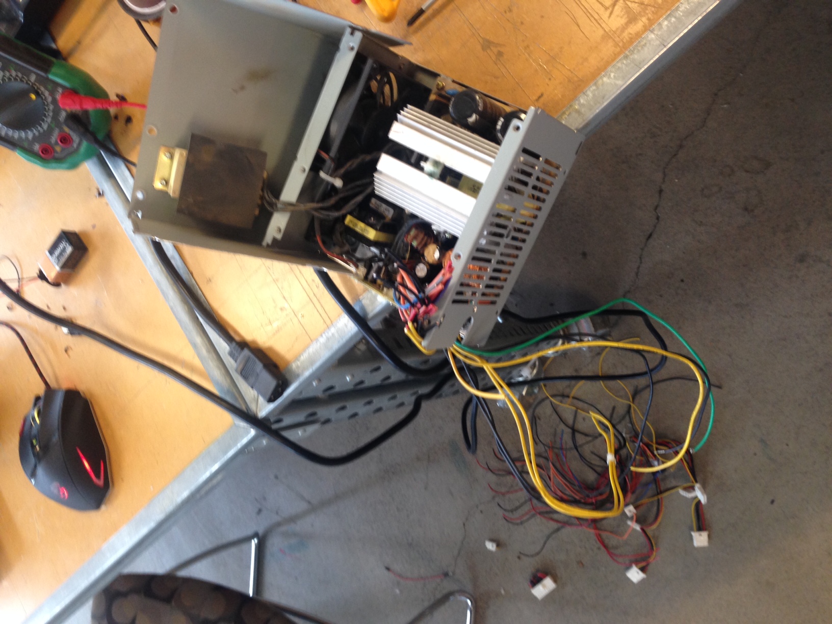
The only other power supply I was able to find was an old PC power supply. I decided to ground it out and then open it up to cut some of the un-needed wires. I cut all of the wires except for the 4 CPU wires, the motherboard red and green wires, and two ground wires. This gave me two 12v lines, one for each of the actuators, a 12v line for the Atmega and lcd, and the green power supply on/off trigger. When I was done I used hot glue to seal the ends of the cut wires and I closed the power supply case. |
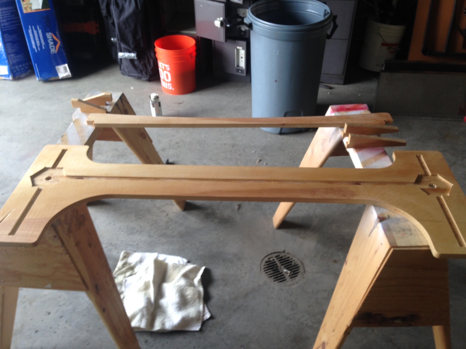
Next I used the same rub on varnish that I used on the top of the desk to coat the bottom of the desk. I did this to bring out the grain of the wood and to waterproof the desk. |
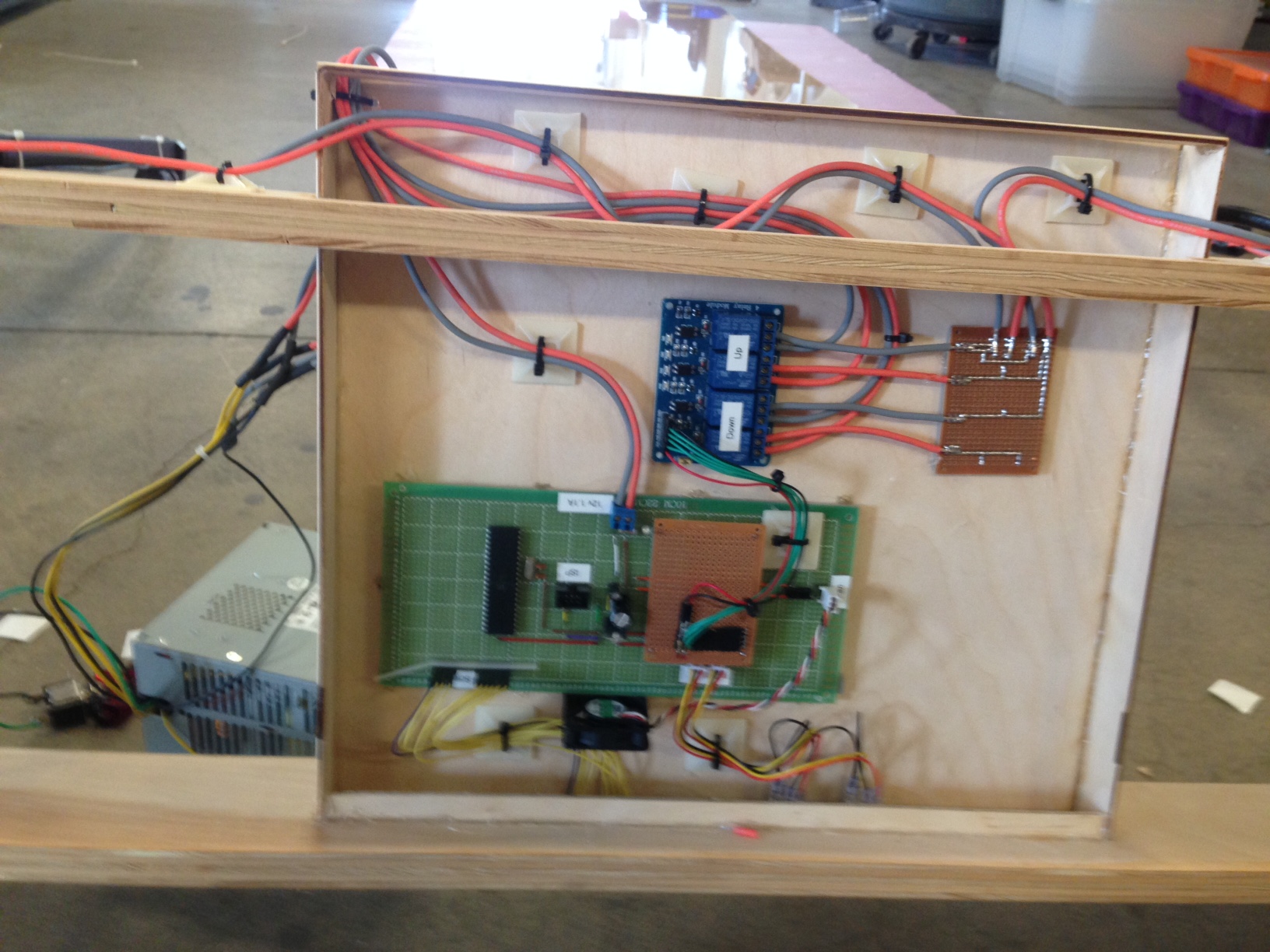
Then I attached the linear actuators to the 3d printed brackets on the top frame of the desk and ran wires from the linear actuator motors to the relay in the electronics holder. I then secured the bottons and lcd in their slots in the front of the electronics holder with hot glue. Then I used 1/4" foam tape to give the bottom of my pcb a cushion and glued the pcb in place. For the relay I used small 3d printed standoffs I designed in Solidworks. |
I then press fit the 3d printed actuator mount into the base section of the desk I cut earlier in the day. It was a close fit but with the dogbones I added to the design in Aspire and the help of a mallet the prints fit nicely. I probably didn't need them, but just in case I added 4 screws in the screw holes of the 3d print to secure it to the base. |
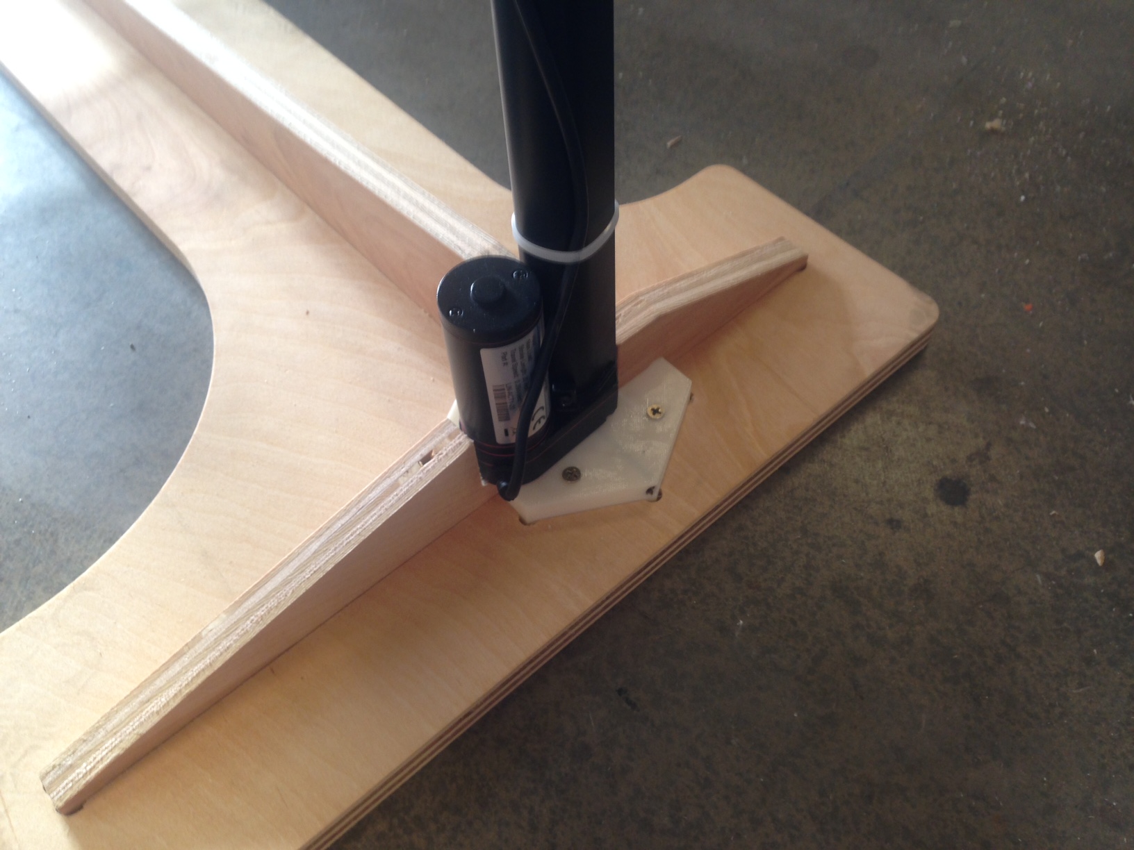
I brushed acytone onto the base brackets just like I did on the top brackets to give them a little extra strength and so they would visually match the top brackets. Then I press fit the bottom of the linear actuators into the print. It was a tight fit, but with the help of a mallet the actuators slid into place. The end result was a very snug fit with little to no flex. Then I glued the vertical base supports in place which help prevent the base from twisting. I also decided to screw the supports in from the bottom through counter sunk holes to provide a little bit of extra strength. |
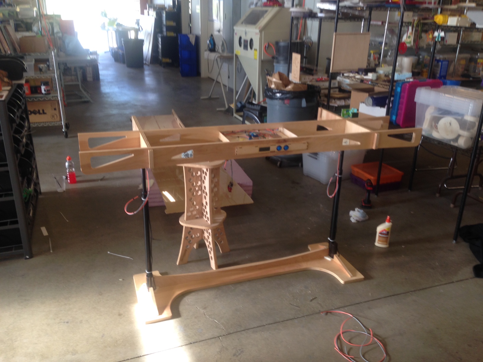
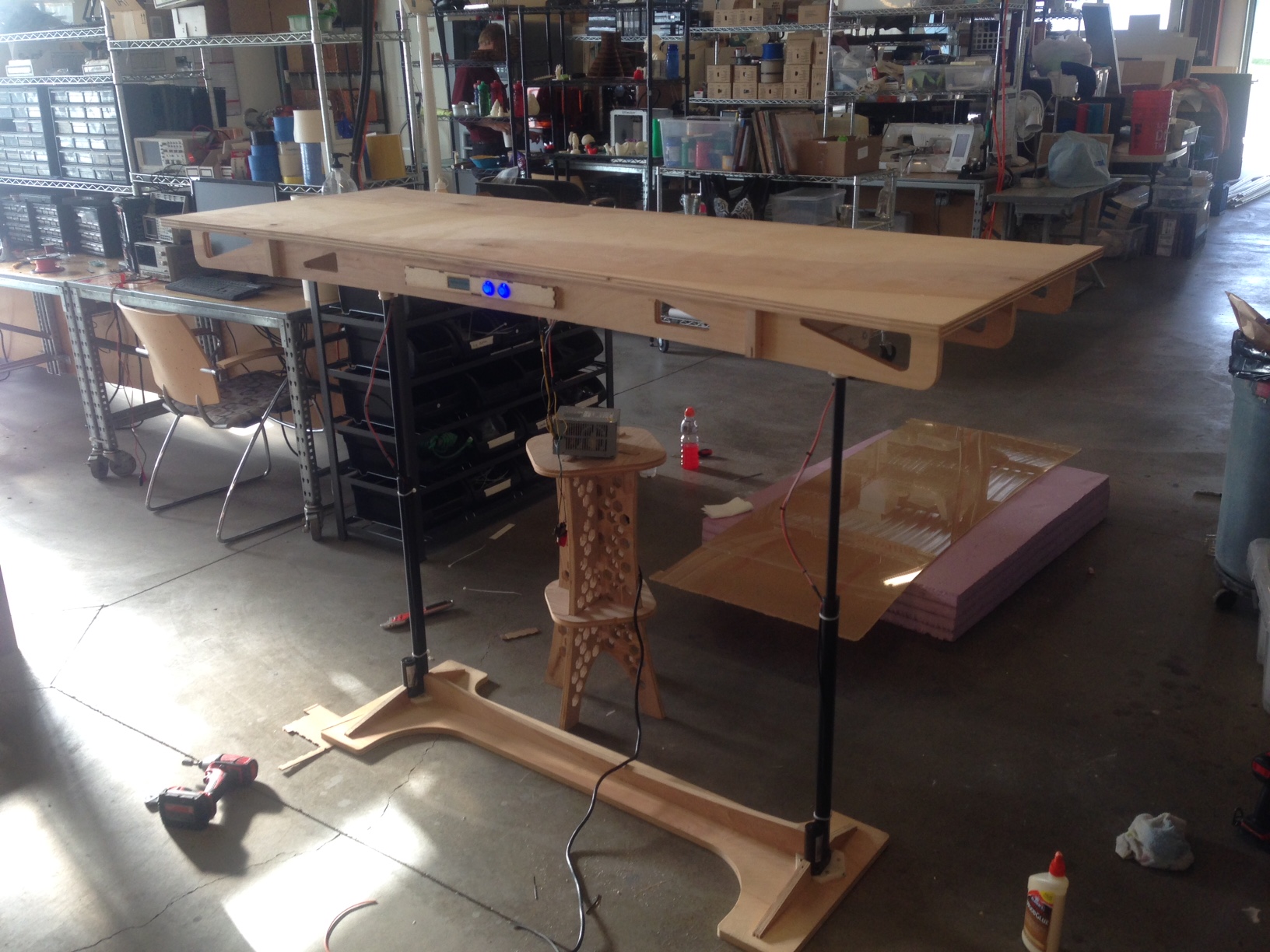
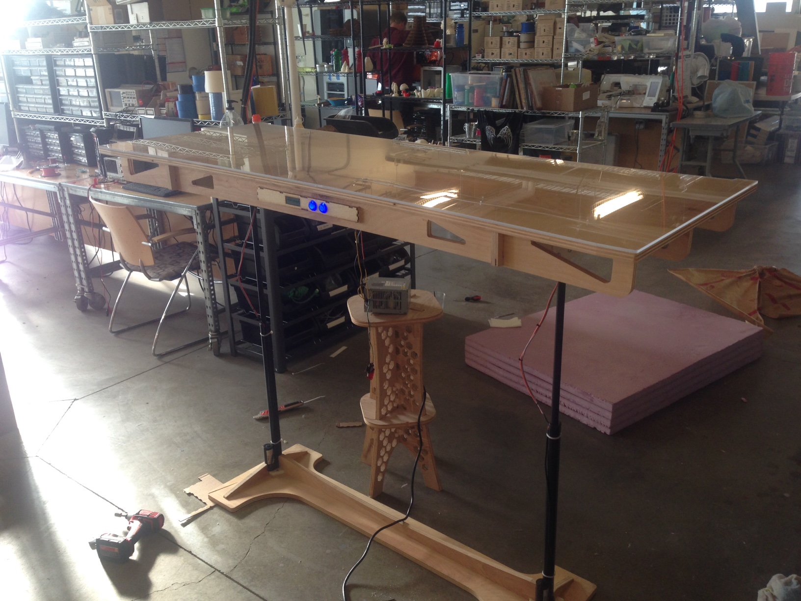
By this point in the day I was ready to put the desk together. I attached the top of the desk to the linear actuators and stood the desk up. It balanced well and I was really happy to see it standing. I would like to get some cable sleeving to cover the power cable to the linear actuator though. The reason I did not put the motor side of the actuators facing up is because of weight. The motors on the actuators are heavy and I did not want to put them on the top if at all possible. Also, the mounting bracket on the bottom of the actuator lended itself much more to the bottom than the cylindrical mounting point on the top. |
Then I added the desk surface itself and tested to make sure the desk could move up and down. Everything worked and was supprisingly stable. The desk only got slighty wobbly when the desk was at full height in standing position. To fix this I have order linear slides which will mount on the wall and attach to the desk where it is put. This was the desk will have more support left to right while still maintaining the ability to move up and down. I could also use cross braces or two more legs but one of my goals with the desk has been to keep the area under the desk here so I can stand, sit, and swing my legs without hitting any support beams under the desk surface. |
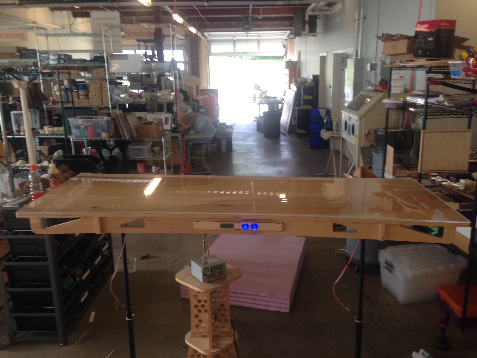
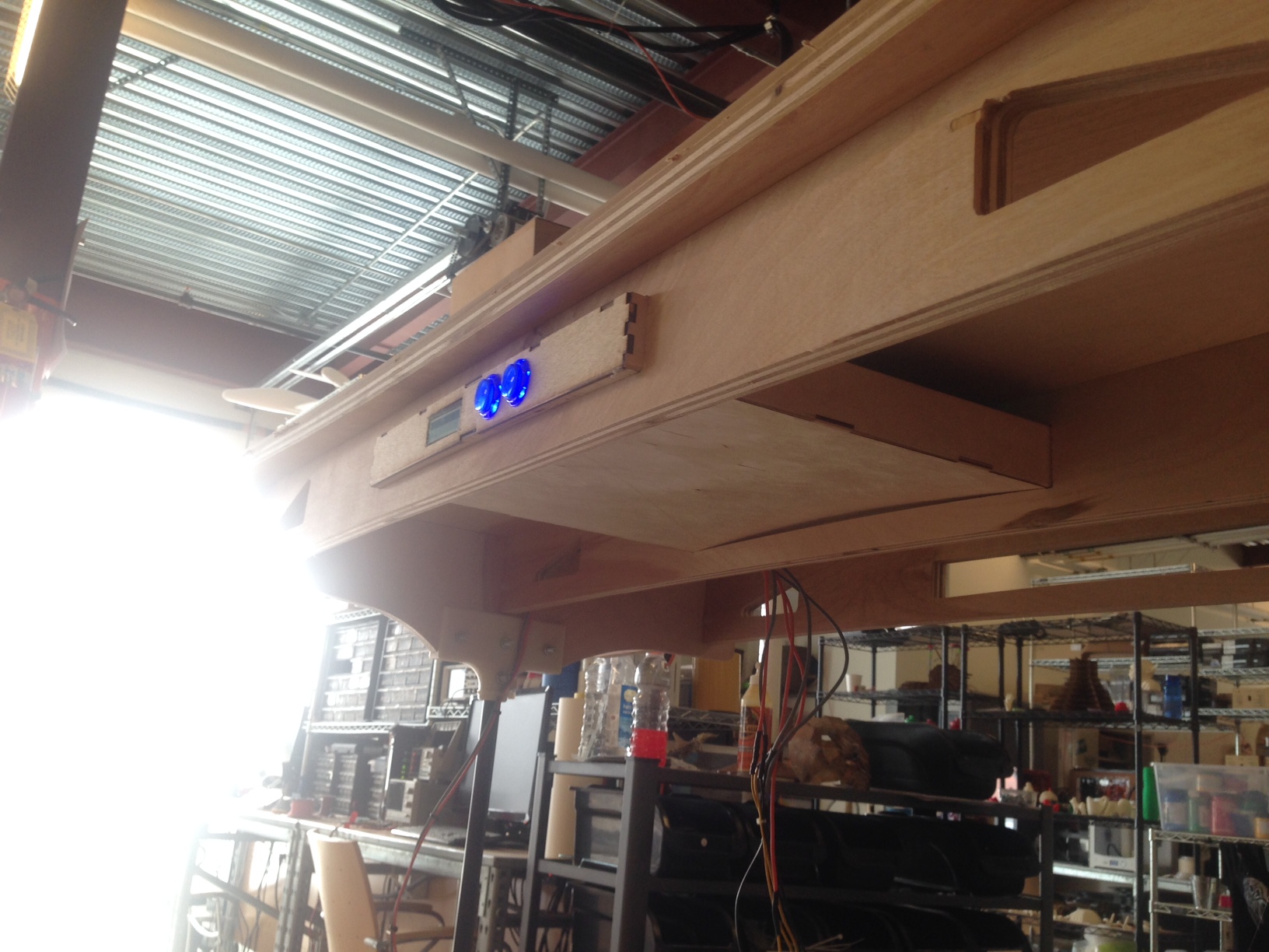
Then I added the acylic sheet I cut for the top which made the desk surface look a million times better adn will help protect the desk. If you notice the power supply is currently just sitting on a stool below the desk. This is because I have ordered another lower profile power supply like the first one that was not working and I will place it inside of the electronics drawer seen on the right. |
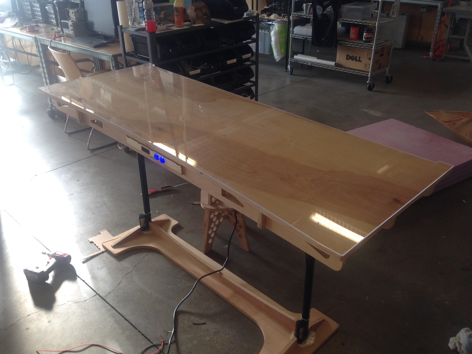
After that the desk was basically done. It moves quickly and smoothly from a sitting to a standing position and back. The desk is stable and will be more than stable enough for a person to sit on once the linear slides arrive and it is set up next to a wall. I am waiting for a power supply to arrive as mentioned earlier. I also ordered some 1/8" siding that will be bent around the edge of the desk surface to give it a nice finish and secure the acrylic in place. Finally I ordered a strip of LEDs at the last minute that I will run along the back edge of the acrylic where I will not put the siding to give the whole acrylic a blue white glow which will look especially cool at night. |
Overall, I really enjoyed this project. I got to used most of the equipment in the Fab Lab, and I got an amazing new piece of furniture out of it. It would have been nice to have had more time for the project so I wouldn't have had to rush so much, but it in the end it all worked out. It's great to finally have the project done and be wrapping up with Fab Academy. |
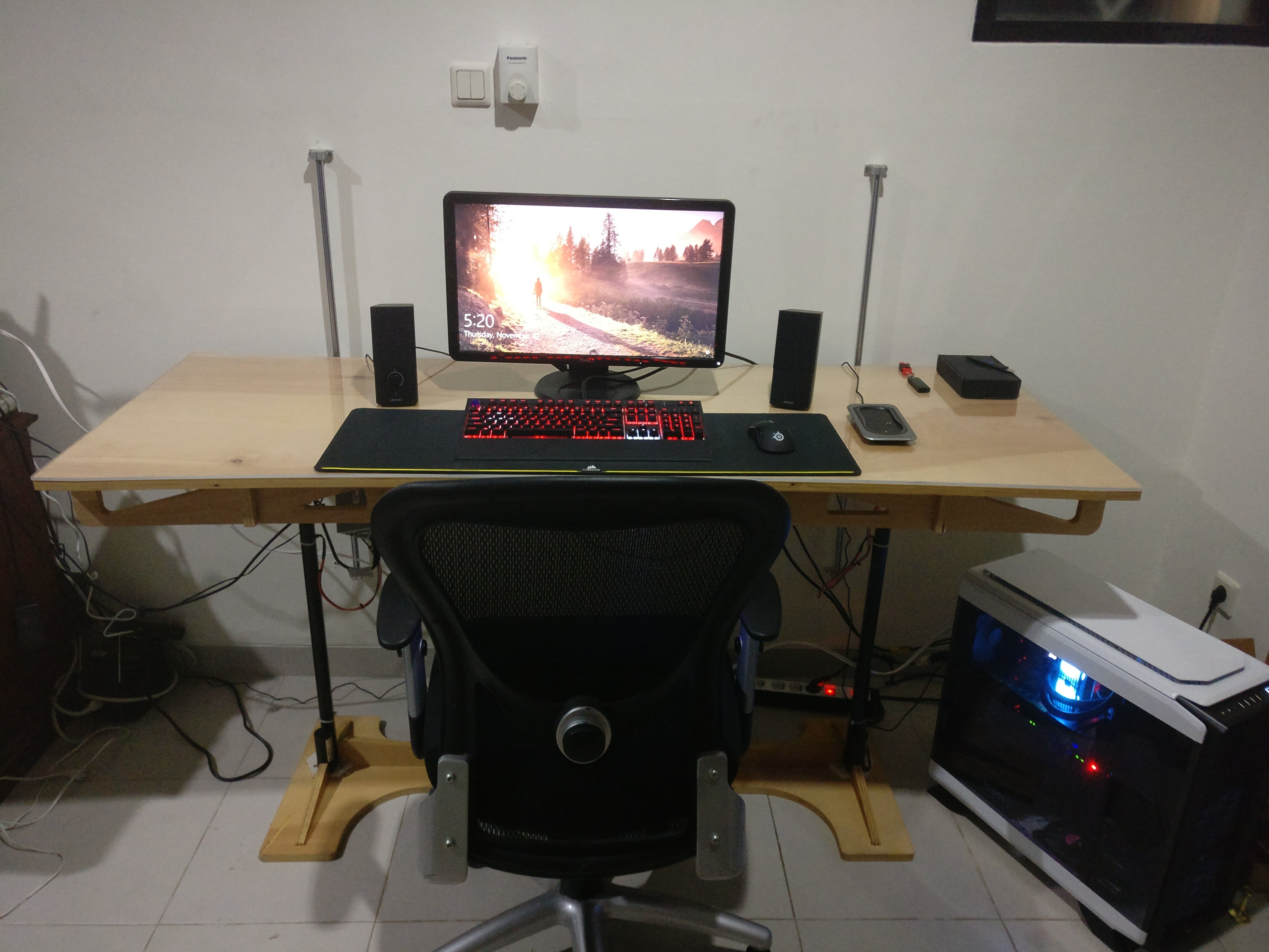
Finally, a few months after I left Alaska I have my desk installed. It is now at my house in Jakarta, Indonesia where I will be living for the next year. I assembled the desk and used CNC linear guide rails to attach the desk to the wall. This prevents the desk from wobbling and still allows for the original vertical up down movement. You can download the bracket I used to attach the desk to the sliders here. |
Having tested the desk for a few days now I am very happy with how it is functioning. I can work standing or sitting which is great, and there is plenty of space for my computer, school work, tools, and anything else I might need to store or work on on my desk. |
Downloads
|